Axl (Diskussion | Beiträge) (→M6 Thumbscrews: + variations) |
Axl (Diskussion | Beiträge) (→Fan Compressor) |
||
| (6 dazwischenliegende Versionen desselben Benutzers werden nicht angezeigt) | |||
| Zeile 8: | Zeile 8: | ||
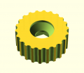
Datei:M6 thumbscrew 002.png|[[OpenSCAD small projects#M6 Thumbscrew]] | Datei:M6 thumbscrew 002.png|[[OpenSCAD small projects#M6 Thumbscrew]] | ||
Datei:Ruler for debugging.png|[[OpenSCAD small projects#Ruler for debugging]] | Datei:Ruler for debugging.png|[[OpenSCAD small projects#Ruler for debugging]] | ||
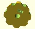
| − | + | Datei:Fan-Compressor 002.png|[[OpenSCAD small projects#Fan Compressor]] | |
</gallery> | </gallery> | ||
| Zeile 43: | Zeile 43: | ||
Datei:M6 thumbscrew 008 (3).jpg|Version 008 | Datei:M6 thumbscrew 008 (3).jpg|Version 008 | ||
Datei:M6 thumbscrew 008 (4).jpg|Version 008 | Datei:M6 thumbscrew 008 (4).jpg|Version 008 | ||
| + | |||
Datei:M6 thumbscrew 002.png|Prototype of Version 007 | Datei:M6 thumbscrew 002.png|Prototype of Version 007 | ||
Datei:M6_thumbscrew_007_(2).jpg|Version 007 | Datei:M6_thumbscrew_007_(2).jpg|Version 007 | ||
Datei:M6_thumbscrew_007_(3).jpg|Version 007 | Datei:M6_thumbscrew_007_(3).jpg|Version 007 | ||
Datei:M6_thumbscrew_007_(1).jpg|Version 007 | Datei:M6_thumbscrew_007_(1).jpg|Version 007 | ||
| + | |||
Datei:5mm thumbscrew cn 007 B.PNG|Variations of Version 007 / M5+lock screw | Datei:5mm thumbscrew cn 007 B.PNG|Variations of Version 007 / M5+lock screw | ||
Datei:5mm thumbscrew cn 007 A.PNG|Variations of Version 007 / M5+lock screw | Datei:5mm thumbscrew cn 007 A.PNG|Variations of Version 007 / M5+lock screw | ||
| + | Datei:5mm thumbscrew cn 007-2.jpg|M5+lock screw on 3D Printer's Z axis | ||
| + | Datei:5mm thumbscrew cn 007-1.jpg|M5+lock screw on 3D Printer's Z axis | ||
| + | |||
Datei:M3 thumbscrew 007 A.PNG|Variations of Version 007 / M3 big wheel | Datei:M3 thumbscrew 007 A.PNG|Variations of Version 007 / M3 big wheel | ||
| + | Datei:M3 thumbscrew 007 B.jpg|M3 big wheel moves 3D print-bed | ||
</gallery> | </gallery> | ||
| Zeile 133: | Zeile 139: | ||
% translate ([0, 0, i]) cube([ruler_length, ruler_thick, ruler_thick], center=true); | % translate ([0, 0, i]) cube([ruler_length, ruler_thick, ruler_thick], center=true); | ||
}</nowiki> | }</nowiki> | ||
| + | |||
| + | |||
| + | == Fan Compressor == | ||
| + | * http://www.thingiverse.com/thing:24487 | ||
| + | <br/> | ||
| + | <gallery caption="Fan Compressor" perrow="4"> | ||
| + | Datei:Fan-Compressor 002.png|Compressor tube | ||
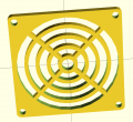
| + | Datei:Fan-Protector 006-1.png|Protective grille | ||
| + | Datei:Fan-Compressor 100 4747.JPG|Fan 70 mm | ||
| + | Datei:Fan-Compressor 100 4746.JPG|Protective grille | ||
| + | Datei:Foto2848.jpg|Printed compressor part | ||
| + | Datei:Fan-Compressor 100 4749.JPG|Protective grille | ||
| + | Datei:Fan-Compressor 100 4750.JPG|Compressor tube | ||
| + | </gallery> | ||
== OpenSCAD Tipps, Tutorials etc. == | == OpenSCAD Tipps, Tutorials etc. == | ||
Aktuelle Version vom 9. Juni 2012, 16:04 Uhr
A collection of smaller projects using OpenSCAD:
Fan protective grille
- The Hackerspace main network switch was quiet noisy.
- Original 40 mm internal fan (5 Volt) was replaced by an external 70 mm & 12 Volt model.
- Running at 5 Volts keeps it at a lower noise level.
- To avoid (further) hurts, the fan needed a grille.
- OpenSCAD Script Datei:Fan-Protector 005.scad
- → render mesh and export in STL format
- → 3D print on yag-freak's Prusa Mendel - thank you!
- → render mesh and export in STL format
M6 Thumbscrews
- version 007: convert a regular M6 nut into a M6 thumbscrew
- version 008: convert a regular M6 screw (DIN 963, ISO 2009, "Senkkopf") and a nut into a M6 thumbscrew
- useful in Zen Toolworks CNC Fräse project for simple tool changes
- Thanx to Byteborg for printing and creation of new screw variations ;-)
- Thumbscrews
//
// M6 thumbscrew
//
// 29.12.2011 - 002 - initial
// 30.12.2011 - 004 - better thumbscrew pattern
// 30.12.2011 - 005 - + test mode
// 01.01.2012 - 007 - adjust M6 hole, adjust nut diameter
//

test = 0;

pi = 3.1415926;

R = 10;			// main radius (mm)

// "diff" cylinders around main radius
rs = 1.25;			// radius cylinders
N = round((R * 2 * pi) / (2.8 * rs)); 	// number
R2 = R + rs / 4;

// hole M6
rh = 3.25;			// radius "hole for M6"

// heights
tt = (test == 0) ? 8.0 : 3.2;		// thickness total
tt2 = tt + 1;

// nut
Dn = 10.1;			// diameter of the nut (!)
Rn = tan(30) * Dn;	// radius of outer circle (from diameter)
tn = (test == 0) ? 4.6 : 2.0;			// thickness


// some debug infos
echo ("main Radius R = ", R);
echo ("diff cylinders N = ", N);


difference () {
	cylinder(r = R, h = tt, center=true, $fn=N * 12);

	cylinder(r = rh, h = tt2, center=true, $fn=50);

	translate ([0, 0, 0.01 + ((tt - tn) / 2) ])
		cylinder(r = Rn, h = tn, center=true, $fa=60);


	for ( i = [1 : 1 : N] )
	{
		assign (a = 360 / N * i)
			translate([R2 * cos(a), R2 * sin(a), 0]) rotate ([0, 0, a]) {
				cylinder(r = rs, h = tt2, center=true, $fn=16);
			}

	}
}
Ruler for debugging
- add a simple ruler to OpenSCAD source code
- optical control - prevent getting lost of orientation and size of the result
- ruler will not be part of STL output etc. (using the % background modifier)
- Source: Datei:Ruler for debugging.scad
//
// rulers - demo
//

# translate ([60, 30, 50]) cylinder (h = 30, r=20, center = true, $fn=30); // sample, only - add your objects here


ruler_grid = 10;  // mm
ruler_digits = 10;
ruler_thick = 0.5;
ruler_length = ruler_grid / 4;

for ( i = [0 : ruler_grid : ruler_grid * ruler_digits] )
{
	% translate ([i, 0, 0]) cube([ruler_thick, ruler_thick, ruler_length], center=true);
	% translate ([0, i, 0]) cube([ruler_thick, ruler_thick, ruler_length], center=true);
	% translate ([0, 0, i]) cube([ruler_length, ruler_thick, ruler_thick], center=true);
}
Fan Compressor
- Fan Compressor


